MK6 User Manual
Full user manual for the MK6 Earthquake Trigger Recorder — installation, wiring, commissioning, maintenance and specifications.
General Description
It's not just the earthquake that causes damage to property — much of the damage is caused by secondary effects such as flooding, fire and explosions. A way of isolating the source of these disasters is an extremely valuable insurance policy. Similarly, expensive machinery can be shut down before it is subject to the full effect of earthquake-generated forces.
An earthquake generates two types of shock waves: pressure waves (P-waves, which produce predominantly vertical accelerations) and shear waves (S-waves). The S-waves do all the damage but travel from the earthquake epicentre more slowly than the P-waves. The P-wave can arrive seconds before the damaging S-waves.
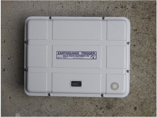
Solid State's Earthquake Trigger continuously monitors all components of the earth's acceleration due to seismic forces. It is designed particularly to detect the faster-moving P-waves. When the acceleration exceeds the pre-set level the output relay changes state until 8 seconds after the quake. Contacts on this relay may be used to initiate any desired action. The unit has an event counter mounted on the lid to record the total number of operations, including instrument test operations.
AC Option
The transformer provides a float charge for the nine-cell Nickel Cadmium backup battery. Should the mains fail, the NiCad battery will power the circuit for approximately 24 hours.
DC Option
Used for DC operation from an external no-break battery system at 24 V DC. This option does not require the internal backup battery.
Installation
Mounting
The site of installation is critical to performance and reliability. Consider all of the following when choosing a site:
- The Earthquake Trigger may be installed horizontally or alternatively vertically.
- It must be installed at a site where it is unlikely to be subjected to false triggering from non-earthquake forces such as motor vehicles or heavy objects dropped nearby.
- Install on a large mass of concrete that is in intimate contact with the earth. A suitable site can usually be found in the foundations of a building.
- The Earthquake Trigger is sensitive to moisture — the environment should be as dry as possible.
A single 6 mm masonry anchor through the hole in the centre of the aluminium base and into the concrete will hold the Earthquake Trigger firmly on its three feet. Do not over-tighten — tighten finger tight then apply approximately ½ a turn with a wrench.
Wiring
Two M16 holes have been provided for cable entry. When removing the lid, be careful of the twisted wires that connect to the counter. Remove the lid just far enough to unplug the connector first.
AC Option — Terminal Strip
| 1 — Earth | 4 — Batt + | 7 — Out 2 Com | 10 — Out 1 Com |
| 2 — Phase | 5 — Batt - | 8 — Out 2 N/C | 11 — Out 1 N/C |
| 3 — Neutral | 6 — (blank) | 9 — Out 2 N/O | 12 — Out 1 N/O |
DC Option — Terminal Strip
| 1 — Earth | 4 — (blank) | 7 — Out 2 Com | 10 — Out 1 Com |
| 2 — Batt + | 5 — (blank) | 8 — Out 2 N/C | 11 — Out 1 N/C |
| 3 — Common - | 6 — (blank) | 9 — Out 2 N/O | 12 — Out 1 N/C |
Commissioning
The sensitivity setting is determined by the application. If false triggering is acceptable but any slight earthquake must be detected, use the more sensitive settings (0.012g or 0.025g). If false triggering is unacceptable and only large potentially damaging earthquakes need to be detected, use the least sensitive settings (0.100g or 0.200g).
Sensitivity is set via a DIL switch accessible through a hole in the internal shield:
- Switch 1 on, all others off — 0.012g
- Switch 2 on, all others off — 0.025g
- Switch 3 on, all others off — 0.050g
- Switch 4 on, all others off — 0.100g
- Switch 5 on, all others off — 0.200g
Maintenance
As earthquakes of sufficient magnitude to trigger the device are rare, set up a regular maintenance schedule to check correct operation. All counter increments should be accounted for and noted in a log — each should be attributed to a test, a false trigger, or an earthquake.
To test the trigger on its most sensitive range, touching the case lightly with a screwdriver will trigger it. With switch 4 on, strike the concrete firmly with a heavy hammer close by. Shock testing should be conducted at installation and every 6 months thereafter.
Specifications
| Power — AC Option | 230 V ±10%, 50 Hz, 3 VA. NiCad battery backup maintains operation for up to 24 hours. |
| Power — DC Option 1 | 24 V DC (+10% / -30%), 20 mA standby. No internal battery backup. |
| Sensitivity | 0.012, 0.025, 0.050, 0.100, or 0.200g (any direction) |
| Frequency Response | Flat 2–10 Hz (±3 dB), 10 dB down at 20 Hz |
| Operation Time | Relay actuated within 10 ms of first qualifying shock. De-energised 8 seconds after last exceedance. |
| Event Counter | 6-digit counter, records all operations |
| Contact Ratings | OMRON LY2 Relay — 10A at 230 VAC, 3A at 24 V DC resistive |
| Weight | 3 kg |
| Size | 290 × 220 mm base, 90 mm high |
| Construction | Cast aluminium casing, white polyester finish |