Earthquake Trigger User Manual
For Serial Numbers 7495 and later (Issue – 1 July 2021)
Contents
General Description
It's not just the earthquake that causes damage to property; much of the damage is caused by secondary effects such as flooding, fire, and explosions. A way of isolating the source of these disasters is an extremely valuable insurance policy. Similarly, expensive machinery can be shut down before it is subjected to the full effect of earthquake-generated forces.
An earthquake generates two types of shock waves: the pressure waves (P‑waves, which produce predominantly vertical accelerations) and the shear waves (S‑waves). The S‑waves do all the damage but they travel from the earthquake epicentre more slowly than the P‑waves. The P‑wave can arrive seconds before the damaging S‑waves.
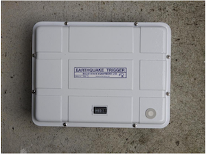
Solid State's Earthquake Trigger continuously monitors all components of the earth's acceleration due to seismic forces. It is designed particularly to detect the faster moving P‑waves. When the acceleration exceeds the pre‑set level, the output relay changes state until 8 seconds after the quake. Contacts on this relay may be used to initiate any desired action. The unit has an event counter mounted on the lid to record the total number of operations, including instrument test operations.
AC Option
The transformer provides a float charge for the nine‑cell Nickel Cadmium backup battery. Should the mains fail, the NiCad battery will power the circuit for approximately 24 hours.
DC Option
This is used for DC operation from an external no‑break battery system 24 V DC. This option does not require the internal backup battery.
Installation
Mounting
- The Earthquake Trigger may preferably be installed horizontally or alternatively vertically.
- It must be installed at a site where it is unlikely to be subjected to false triggering signals generated by non‑earthquake forces such as vehicles or dropped objects.
- The device should be installed on a large mass of concrete in intimate contact with the earth, such as a building foundation.
- The Trigger is sensitive to moisture—its environment should be as dry as possible.
A single 6 mm masonry anchor through the centre hole of the aluminium base into concrete will secure the unit firmly on its three feet. Anchor bolts should be finger‑tight plus a half‑turn with a wrench—do not overtighten, or you risk damaging the cast‑aluminium case.
Wiring
Two M16 holes are provided for cable entry. Use a bung on unused entries. When removing the lid, disconnect the counter connector before lifting—do not strain the wires. Ensure cables aren't trapped under the lid when re-sealing. For AC option, maintain mains supply at least 18 hours per 24 hours. For DC option, provide continuous supply.
AC Option: Terminal Strip Wiring
| Terminal | Function |
|---|---|
| 1 | Earth |
| 2 | Phase |
| 3 | Neutral |
| 4 | Batt + |
| 5 | Batt – |
| 6 | – |
| 7 | Out2 Com |
| 8 | Out2 N/C |
| 9 | Out2 N/O |
| 10 | Out1 Com |
| 11 | Out1 N/C |
| 12 | Out1 N/O |
DC Option: Terminal Strip Wiring
| Terminal | Function |
|---|---|
| 1 | Earth |
| 2 | Batt + |
| 3 | Common – |
| 4, 5, 6 | – |
| 7 | Out2 Com |
| 8 | Out2 N/C |
| 9 | Out2 N/O |
| 10 | Out1 Com |
| 11 | Out1 N/C |
| 12 | Out1 N/O |
Commissioning
Sensitivity should match application: use settings of 0.012 g+ for maximum sensitivity, or ≤ 0.2 g to avoid false triggers. Sensitivity is set via the internal DIP switch accessible through a hole in the PCB shield.
Maintenance
Regular maintenance is recommended since true earthquakes are rare. Log every counter increment—note whether it was a test, false trigger, or actual event. If false triggers are frequent, consider reducing sensitivity or improving mounting site.
Specifications
Specifications
- Power Supply Requirements:
- AC Option: 230 V ±10% 50 Hz sine wave, 3 VA. Includes NiCad battery backup providing up to 24 hours of operation during mains failure.
- DC Option 1: 24 V DC (+10%, –30%) at 20 mA standby.
- DC Option 2: DC options do not include internal battery backup.
- Sensitivity: Selectable via internal switch: 0.012, 0.025, 0.050, 0.100, or 0.200 g. Sensitivity applies to acceleration in any direction. (1 g = 9.8 m/s² or 1000 mg)
- Frequency Response: Flat from 2 Hz to 10 Hz (±3 dB); 10 dB down at 20 Hz.
- Operation Time: Relay actuates fully within 10 ms after detecting three shocks exceeding the threshold. De-energises 8 seconds after the last qualifying acceleration.
- Event Counter: Six-digit counter records all operations including tests, false alarms, and earthquakes.
- Contact Ratings: Omron LY2 relay — 10 A at 230 V AC; 3 A at 24 V DC (resistive); 2 A at 24 V DC (inductive); 0.6 A at 110 V DC (resistive); 0.4 A at 110 V DC (inductive).
- Weight: 3 kg
- Size: 290 × 220 mm base, 90 mm height
- Construction: Heavy-duty cast aluminium casing with white polyester finish.